
Water shutoff planning
Prepare the Site Before a Water Shutoff Installation
This is a planning guide, not a plumbing procedure. Capture the existing valve, pipe layout, access, utilities, and response requirements so an installer can define the correct scope.
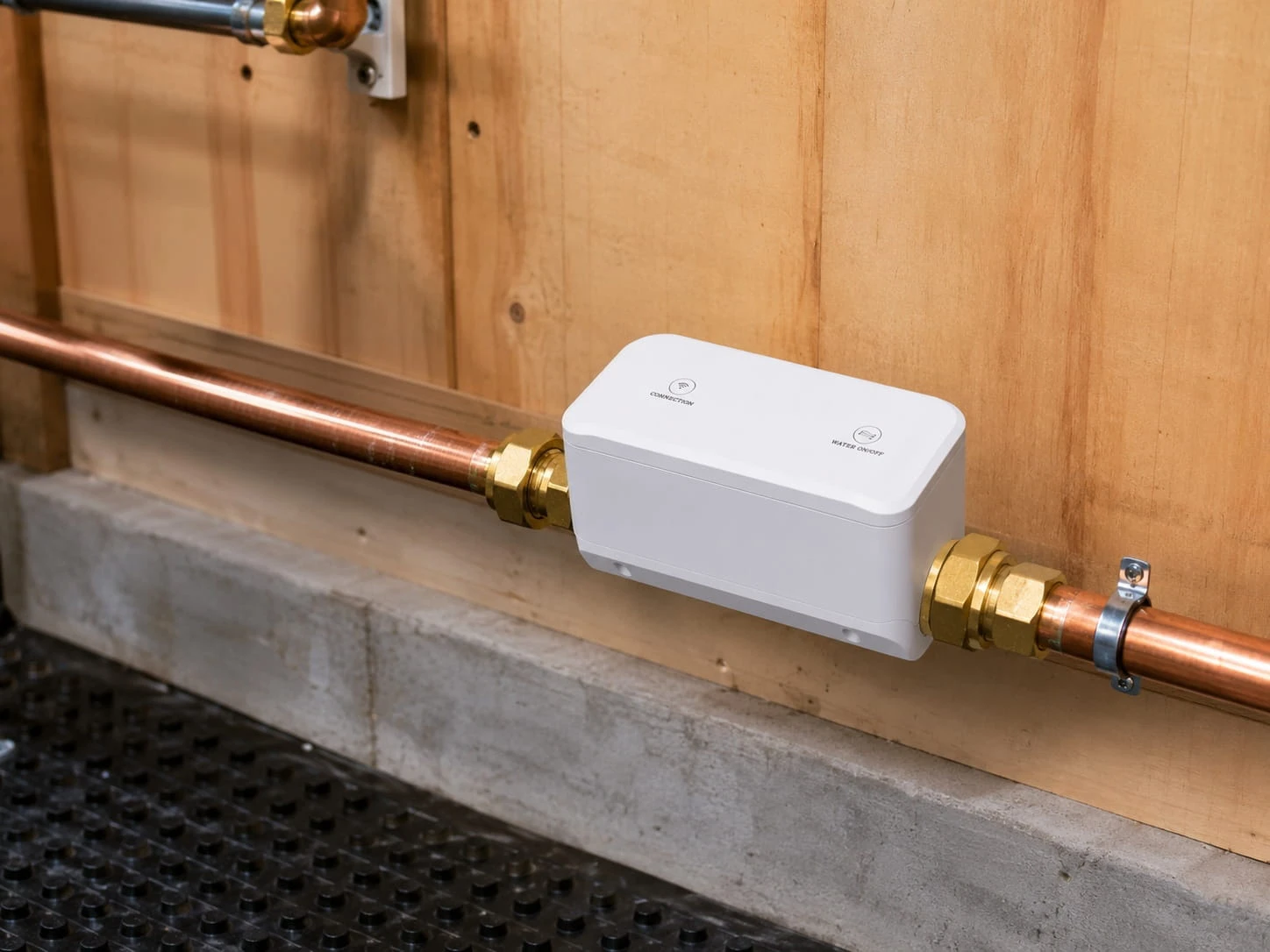
Installation starts with site evidence, not an online fit guess.
Record the existing valve and pipe context, dimensions, clearance, access, condition, nearby power and network conditions, desired sensing and control roles, and local installation requirements. A qualified installer must determine the actual work, components, testing, and safe restoration process.
Bring these four evidence groups to the installer.
Valve record
Clear photos, valve type, handle movement, dimensions, labels, condition, and whether it fully closes.
Pipe and clearance
Pipe size and material, orientation, nearby fittings, branches, wall distance, access, and service space.
System requirements
Detection locations, desired response, power, network, app or gateway, alerts, and manual fallback.
Project ownership
Installer scope, permits or local rules, commissioning tests, maintenance, alert owner, and restoration authority.
01
Photograph the whole installation context, not only the handle.
Capture wide views that show the main line and surrounding space, plus close views of the valve, markings, handle, fittings, and obstructions. Include a measurement reference without disassembling or operating unsafe plumbing.
Note access panels, finished surfaces, moisture, corrosion, insulation, nearby electrical equipment, and any uncertainty about which valve controls the building supply.
02
Mechanical compatibility includes movement, clearance, service, and fallback.
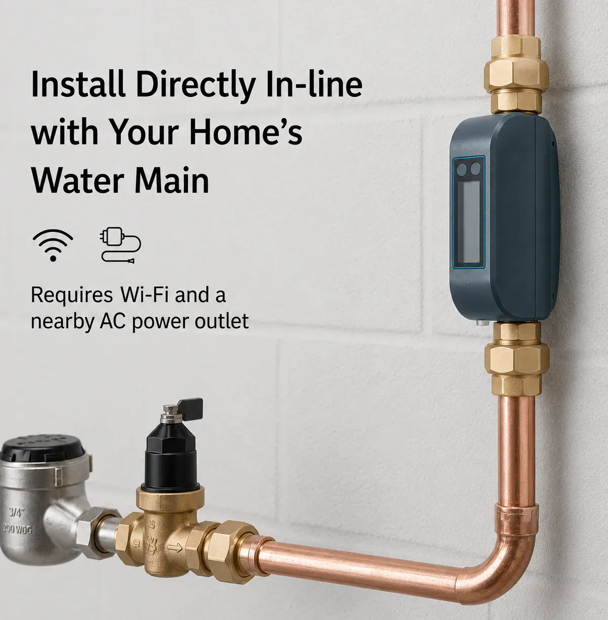
A component must match the documented installation method and leave enough room for operation, fastening, cables, testing, service, and any supported manual control. Pipe condition and valve behavior may change the project scope.
| Area | Evidence to capture | Installer decision |
|---|---|---|
| Existing valve | Type, dimensions, handle travel, labels, condition, closing behavior | Compatible actuation path, valve work, or replacement scope |
| Pipe | Size, material, orientation, branches, fittings, pressure context if known | Approved component and plumbing method |
| Clearance | Wall distance, obstructions, access panels, service space | Mounting, operation, and maintenance feasibility |
| Utilities | Power, network coverage, gateway or app requirements | Supported electrical and connectivity scope |
| Operations | Alert owner, local responder, manual fallback, restoration authority | Commissioning and responsibility procedure |
03
Specify which parts provide sensing, control, connectivity, and power.
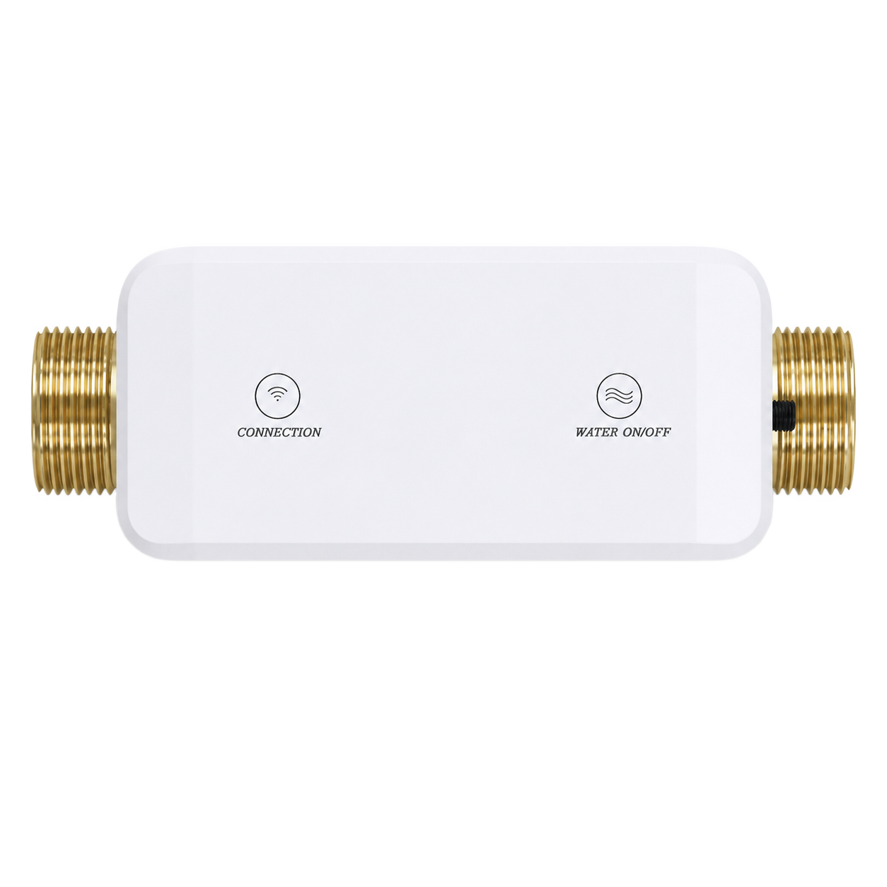
A project may include a valve or actuator, one or more detectors, an app or gateway, power components, mounting hardware, and installation materials. Confirm the current kit contents and compatibility rather than treating a styled bundle image as a bill of materials.
Flow-control component
Match the documented component to the installer-approved valve or inline plumbing path.
Detection components
Choose sensing locations and form factors around realistic water paths.
Connected path
Verify current account, app, gateway, network, notification, and command behavior.
Installation materials
Let the installer define approved fittings, supports, electrical work, and site-specific materials.
04
The project is not finished until behavior and ownership are tested.
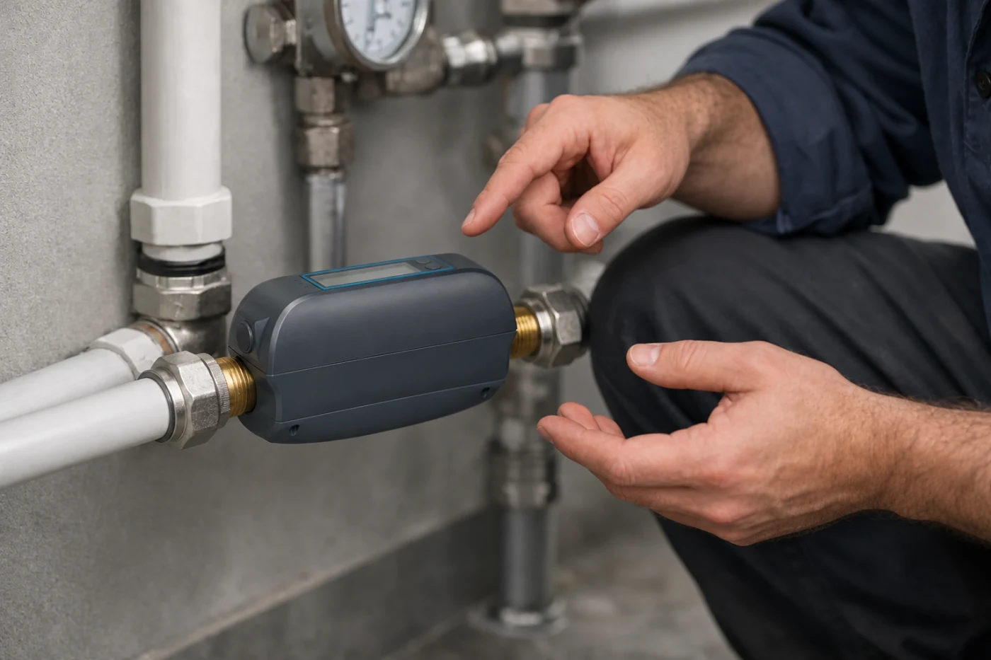
Commissioning should follow the applicable product instructions and the installer's scope. Record supported sensor tests, alerts, valve behavior, connectivity, account access, power recovery, manual fallback, maintenance, and the conditions for restoring water service.
-
Verify the installation
Confirm the completed mechanical, electrical, network, and device setup against the agreed scope.
-
Test supported events
Run the documented detector, alert, control, and recovery checks without creating an unsafe condition.
-
Train the owners
Show the property owner and responder how to check device status, escalate, maintain the system, and use the fallback plan.
-
Record responsibilities
Keep device locations, documents, contacts, tests, account ownership, and restoration authority together.
05
Questions people ask before the next step
Is this a do-it-yourself installation guide?
No. It is a site-record and decision guide. A qualified installer must determine the plumbing, electrical, mounting, commissioning, and local-compliance work.
Can I confirm fit from the valve handle shape?
No. Valve type, dimensions, travel, condition, pipe context, clearance, installation method, power, connectivity, and service access all matter.
What photos should I provide?
Provide wide views of the main line and surrounding space, close views of the valve and markings, handle travel and clearance, nearby fittings, pipe context, obstructions, and a safe measurement reference.
What should be documented after installation?
The installer should document the installed scope, supported tests, app or gateway setup, notification recipients, fallback, maintenance, local response, and restoration responsibility.
Give the installer enough context to define the real scope.
Prepare the valve record, pipe and clearance evidence, utility conditions, system roles, and response ownership before requesting the partner-supported kit.